SAFE, or Systematic Analysis of Faults and Errors, is a hazard analysis process for software- and hardware-based systems that is based on (and designed to work with) System Theoretic Process Analysis (STPA). While STPA excels at the analysis of sociotechnical systems, my research looks at the application of SAFE to non-sociotechnical elements of systems. There are two documentation formats for the analysis, a manual version (M-SAFE) which uses spreadsheets, and a tool-supported version (T-SAFE) which uses AADL to integrate the analysis with a semiformal description of a system’s architecture. The full explanation of SAFE is available in Chapter 4 of my dissertation.
Overview
Process
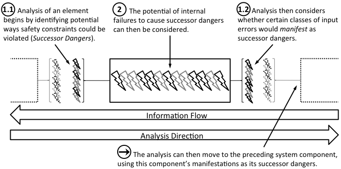
At its core, SAFE is a backwards-chaining analysis consisting of three activities. Activity 0 is performed once per system, while Activities 1 and 2 are performed recursively throughout a system’s specification:
- Defining a system’s fundamentals, which consists of:
- Specifying notions of loss (accidents), ways those losses can occur (hazards), and constraints that prevent the occurrences (safety constraints).
- Specifying the individual system elements (components and connections) that make up the system and how they fit into the system’s control structure.
- Examining an individual element’s interactions, by:
- Defining the element’s individual notion of loss / undesirability (its successor dangers).
- Considering if various classes of input errors (i.e., messages that are late, early, never arrive, have a wrong value, etc.) would be unsafe (termed manifestations).
- Mapping the element’s manifestations to its successor dangers: these are the element’s unsafe interactions.
- Examining an individual element’s internal faults, by:
- Considering the removal of entire classes of internally-caused problems (faults) based on various properties of the element (e.g., if it’s implemented in hardware or software, if other controllers interact with it, etc.).
- Considering if various classes of faults (i.e., development faults, adversaries gaining access to the element, physical deterioration, etc.) would be unsafe
- Mapping the unsafe faults to the element’s successor dangers: these are the element’s internally-caused dangers.
Example
As an example, consider an electric tea kettle. The first few steps an analyst would go through when analyzing the system would be:
- Fundamentals:
- Accident: Kettle base is damaged or destroyed.
- Hazard: Kettle base overheats and melts.
- Safety Constraint: Heating element should be disabled above 100°C
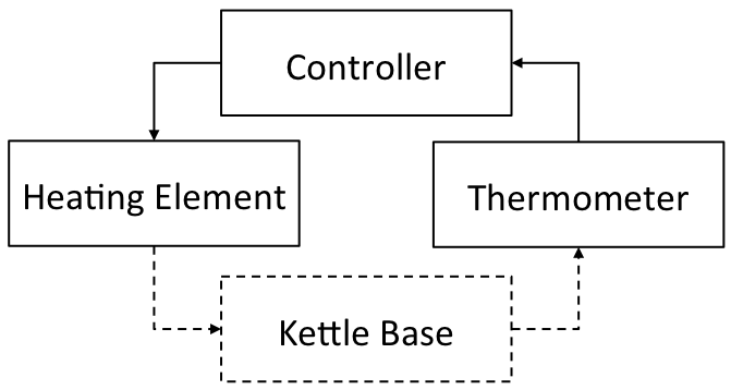
- Control Structure: The core control loop is shown below. Note that the thermometer, controller and heating element are inside the system boundary, while the kettle base is the controlled process and so is considered part of the environment.
- Analysis begins at the first element inside the system boundary: the heating element.
- Successor Danger: Running when the kettle’s temperature is ≥ 100°C
- Note that the first element’s successor dangers are the system-level hazards, other elements will use their successor’s manifestations.
- Manifestations: The following unsafe input guidewords would manifest as the successor danger:
- Late: The toggle-state command is late when the heating element is running and the temperature is ≥ 100°C
- Halted: The toggle-state command never arrives when the heating element is running
- Erratic: An inappropriate toggle-state command arrives when the heating element is off and ≥ 100°C
- Note that these manifestations assume that the controller produces binary “toggle state” commands — if it produced value-based commands (e.g., run for 10 seconds) then we would also need the “High” manifestation.
- Successor Danger: Running when the kettle’s temperature is ≥ 100°C
- At this point the analyst has a choice between the following options (any or all options can be performed at this point, further analysis can be done in parallel):
- Document Unsafe Interactions: Fully document how the manifestations map to the successor danger and specify any possible detection / compensation steps.
- For example, the analyst would explain how the late arrival of a toggle-state command could, in certain worst-case situations, lead to overheating the kettle base. The analyst would then also document any possible compensatory actions, like an auto-off timer.
- Chain Backwards: Move analysis to the controller, using the manifestations as its successor dangers
- Here, the analyst would repeat Activity 1, but this time consider the controller. As the controller can’t directly overheat the kettle base, it uses the heating element’s manifestations as its successor dangers. That is, the controller must not produce late commands, stop sending commands, or produce erratic commands.
- Consider Faults: Analyze how internal failures of the heating element could cause the successor danger even if the controller’s input is correct.
- Here the analyst would perform Activity 2 on the heating element, considering what would happen if, for example, the heating element deteriorated over time.
- Document Unsafe Interactions: Fully document how the manifestations map to the successor danger and specify any possible detection / compensation steps.
Manual Process (M-SAFE)
Full Process and Worksheets
There are two documents which should be used to perform SAFE: the full process specification and blank worksheets. Both are available in standalone formats or Google Docs, though the latter should be used if possible since the technique continues to be refined.
Full Example
There is also a fully-worked example based on a medical application called the “PCA Interlock Scenario.” Most of my publications contain short descriptions of the scenario, or there’s a full description of the problem and proposed solution here.
Tool-Assisted Process (T-SAFE)
The annotations and properties used for T-SAFE are provided in a more developer-friendly format in the MDCF-Architect‘s documentation.